
I bought this camera a few years ago when I was interested in looking at a few different available opens that were cheap AF on Amazon.
I wanted to look at an RF based Baby monitor and an IP based Baby Monitor. The RF version was the one that I blogged about on my personal blog.
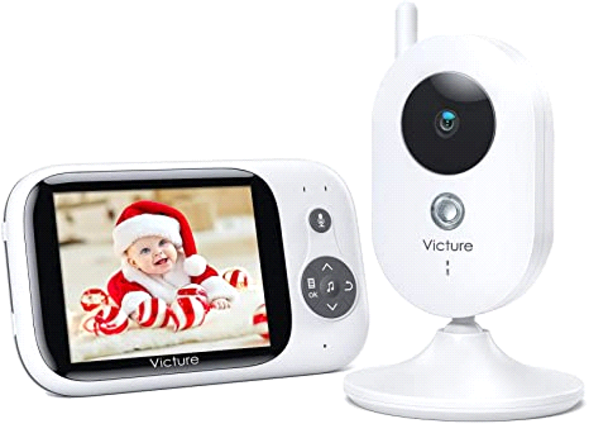
Victure BM32 Baby Monitor
Blog is here: https://noobiedog.com/the-tale-of-two-victure-baby-monitors/
The IP version is this one.

Features:
· Motion/Sound Detection
· Cloud/SD Storage
· 2-Way Audio
· 1080P Night Vision/ Sharing Account
· Home & Away Mode
Pretty standard for any IP camera now days. However, it was cheap, and looked like it may be mass produced from China. Cheap and China generally mean insecure, because the R&D into securing a device just isn’t part of the development process.
So, in fact the camera is made by a different firm and is located in China!
Manufacturer: ShenZhen Longtour Photology Co. Ltd
Model: TC100
FCCID: https://fcc.report/FCC-ID/2AQNX-TC100/
So, I bought it. When it turned up, I didn’t even turn it on, I just opened it up as well…. That’s where I knew I would end up anyways... that was mistake #1!
After opening I always take photos of the board, both sides of any additional boards too, and generally id take photos of the casing too. (always good for blogging)
Let’s peek inside.
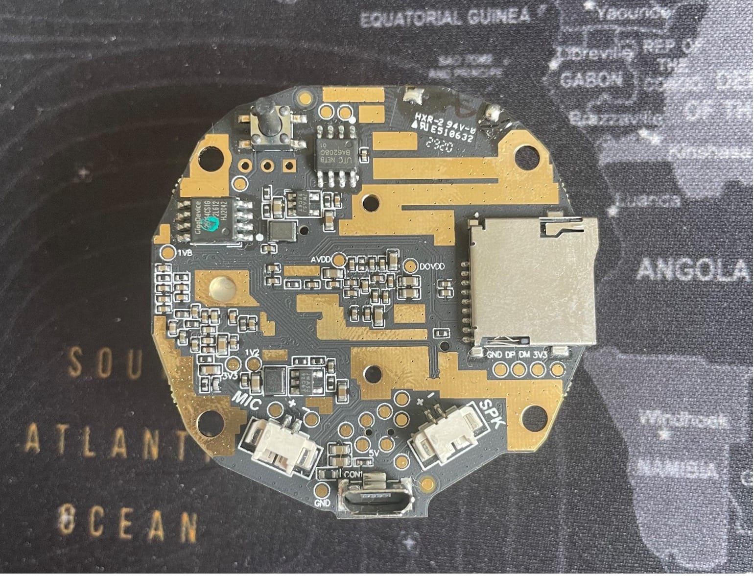
Underside:
· SPI Flash
· Button
· SD Card Slot
· USB Micro Connector
· Test Points
· Connection headers
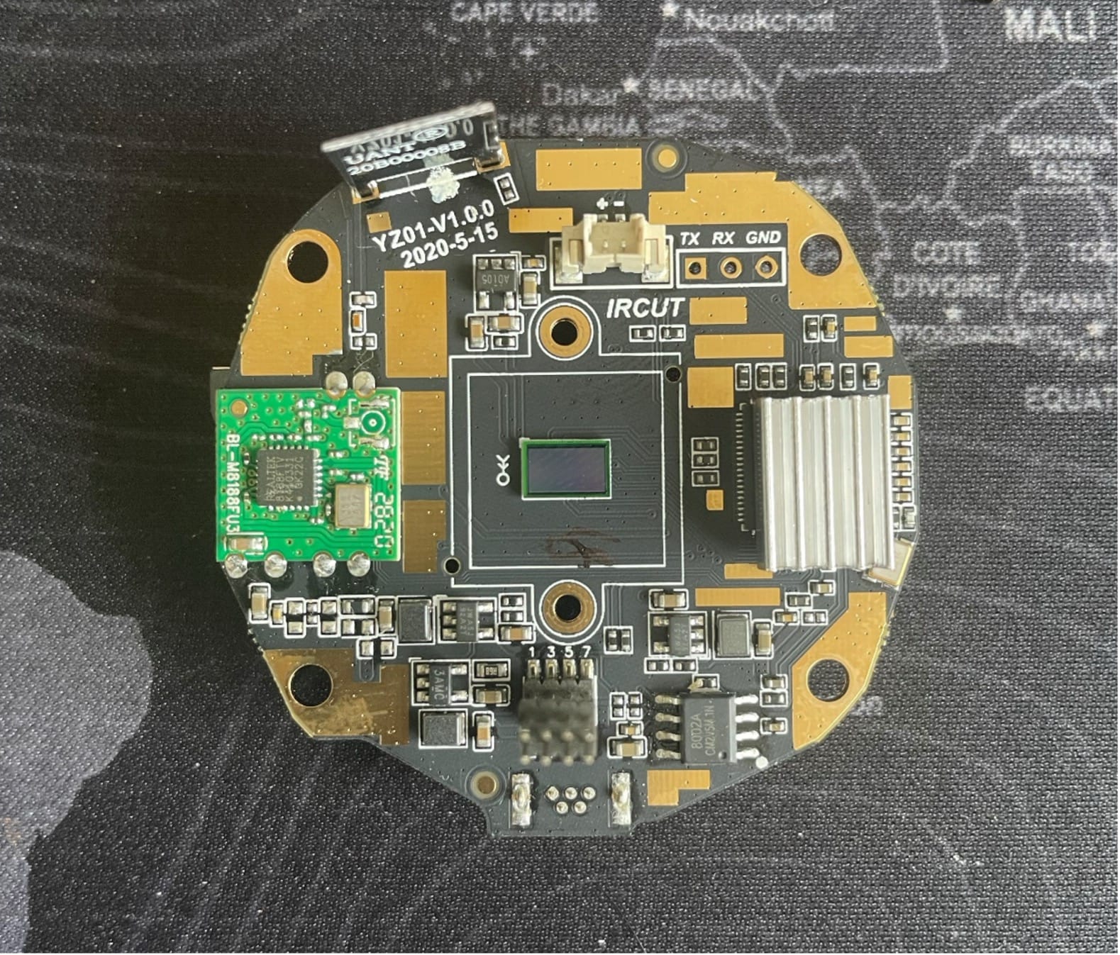
Topside:
· Wi-Fi Controller Board
· 2.4ghz Antenna
· Debug Headers
· Photo Sensitive IC
· Heatsink
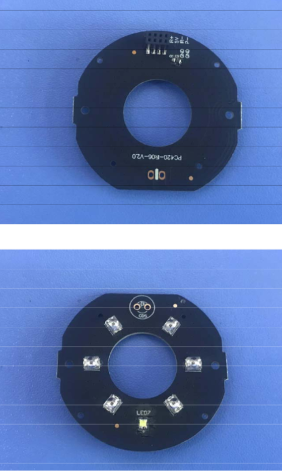
Additional board:
· (IR LEDS)
Debugging:
So, one of the first things that stands out is the 3 Pin Debug header. This strait away screams UART (however it’s not always the case, but in this, it is as its marked with GND, RX, TX)
The SPI flash is also of interest, as it means they are using external memory for storage. The good thing about SPI flash storage, even an Arduino/RPi can extract the flash in most cases!
I ended up soldering some header pins to the through holes on the PCB for the UART and plugged my USB-UART adaptor in. (Remembering to cross over the TX->RX and RX->TX)
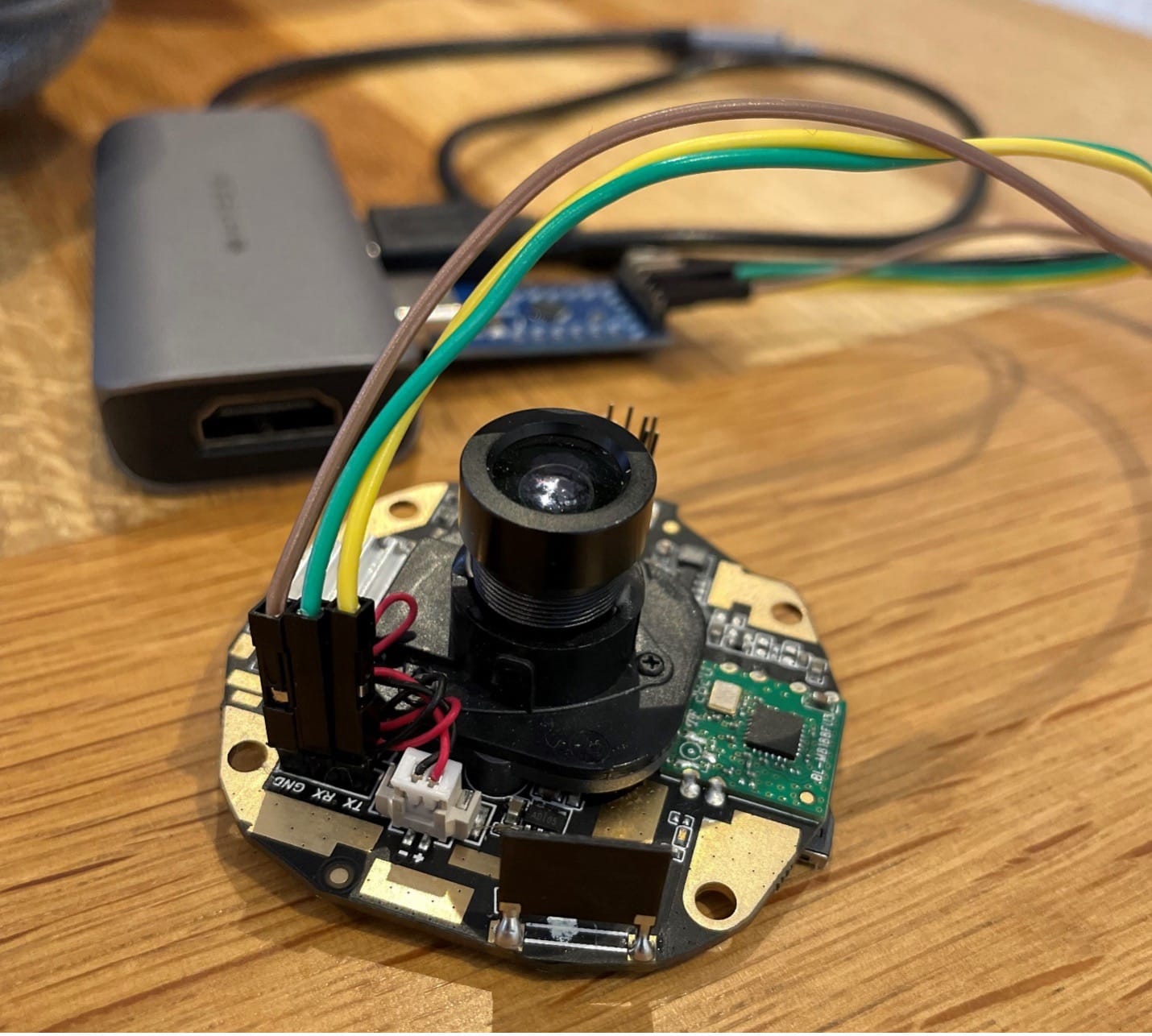
Once the USB dongle is plugged in and a Serial Shell has been initiated (I use MobaXterm Paid Version) I plug in the power cable and hope some magic happens!
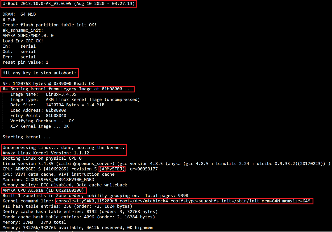
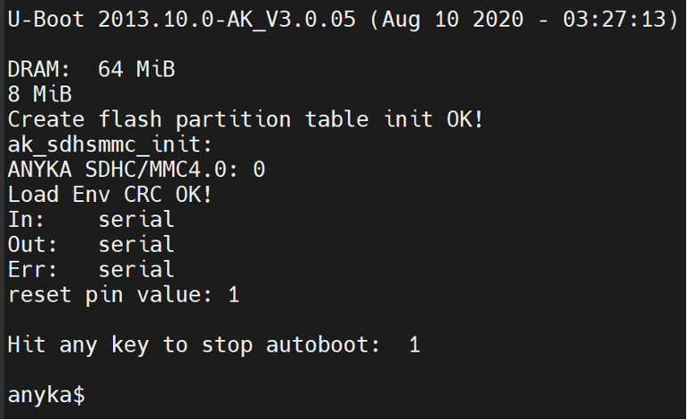
Fortunately, the UART worked instantly lol, and gives a tonne of useful information! I have highlighted some interesting parts in red! What we are not seeing here is the U-Boot SPL. U-Boot SPL starts followed by U-Boot, and finally the kernel.
U-Boot 2013.10.0-AK_V3.0.05
I mean I know U-Boot is old, but still 10 years old in this instance. (Yes, it is still maintained, here is the legit repo https://github.com/u-boot/u-boot)
So, are there any vulns with this old ass version? YES actually, yes there is! https://www.cvedetails.com/vulnerability-list/vendor_id-18843/product_id-48033/Denx-U-boot.html
Hit any key to stop autoboot:
This shows us that there is possible access to the U-Boot Shell. From there you can add custom kernel arguments by adding arguments to the bootargs variable. For example, to bypass the installed init system and drop to a root shell :D
Uncompressing Linux... done, booting the kernel.
Anyka Linux Kernel Version: 1.1.12
This is where the U-Boot has done its job and passing now over the Linux subsystem.
Below is the actual process that happens from U-Boot to Linux/subsystems. From the text in the Serial output, this is Stage 5.
- CPU Startup: After applying power to the system, the CPU begins executing its reset vector, which initializes the CPU as well as the peripheral components.
- Boot ROM Code: The CPU starts executing boot code stored in the read-only memory (ROM). This code is responsible for initializing the hardware and loading the bootloader.
- Bootloader Load: The Boot ROM code reads the bootloader (U-Boot) from a non-volatile storage device, such as a NAND flash, into the system memory.
- Bootloader Initialization: U-Boot initializes itself and the hardware, setting up the environment for loading the OS.
- Operating System Load: U-Boot reads the OS image from non-volatile storage into memory and passes control to the OS.
- Operating System Initialization: The OS initializes itself, configures the hardware and starts the user interface or application.
ARMv5TEJ
This is the ARM architecture used on this chipset. This information helps if/when trying to reverse engineer any binaries we may come across.
|
ARMv5TEJ |
Thumb, Jazelle DBX,
enhanced DSP instructions |
Variable, TCMs, MMU
|
220 MIPS @
200 MHz |
ANYKA CPU AK3918 (ID 0x20160100)
This is an indicator for the CPU being used, fortunately for us, the ANYKA CPU is a specific brand used in a lot of cheap IP Cameras
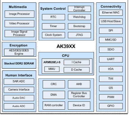
AK3918 HD IP Camera SoC Specification
http://monitor.espec.ws/files/700cafec77419c2d7705f376c974b8d0ff72_986.pdf
Kernel command line:
console=ttySAK0,115200n8 root=/dev/mtdblock4 rootfstype=squashfs init=/sbin/init mem=64M memsize=64M
The final part that is highlighted in the screenshot is the Kernal Command line. This is part of the Linux Kernal.
Let’s have a quick look at the parameters.
console=ttySAK0,115200n8
The Linux kernel is configured to select the console by passing it the console parameter.
With no console parameter the kernel will use the first virtual terminal, which is:
/dev/tty0.
In this instance, the console option tells the kernel to use ttySAK0 (the first serial port), with settings of speed=115200 cps, no stop bits and 8 data bits.
root=/dev/mtdblock4
This argument tells the kernel what device is to be used as the root filesystem while booting.
/dev/mtdblock4 in this instance is the SPI flash.
rootfstype=squashfs
The 'rootfstype' argument tells the kernel to mount the root filesystem as the file type specified.
Squashfs is a compressed read-only filesystem for Linux.
It uses zlib, lz4, lzo, or xz compression to compress files, inodes and directories. Inodes in the system are very small and all blocks are packed to minimise data overhead. Block sizes greater than 4K are supported up to a maximum of 1Mbytes (default block size 128K).
Squashfs is intended for general read-only filesystem use, for archival use (i.e., in cases where a .tar.gz file may be used), and in constrained block device/memory systems (e.g. embedded systems) where low overhead is needed.
init=/sbin/init
Once the kernel has started, it starts the init process, a daemon which then bootstraps the user space, for example by checking and mounting file systems, and starting up other processes. The init system is the first daemon to start (during booting) and the last daemon to terminate (during shutdown).
The above argument is telling the Linux kernel where init resides. (/sbin/init)
A famous hack here is to replace the content of this variable with init=/bin/sh. Depending on the presence of the /bin/sh binary and other parameters, we could obtain a shell which would be limited but more than enough to dig into the file system of the device and its functionalities.
mem=64M memsize=64M
These are set for memory management.
Now that we have a fair bit of info from the boot sequence. What is the device trying to do?
After the boot sequence, it partitions out the SPI flash into different sections.
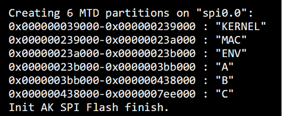
This again is useful, so if/when we extract the SPI flash. We can use these values 😊
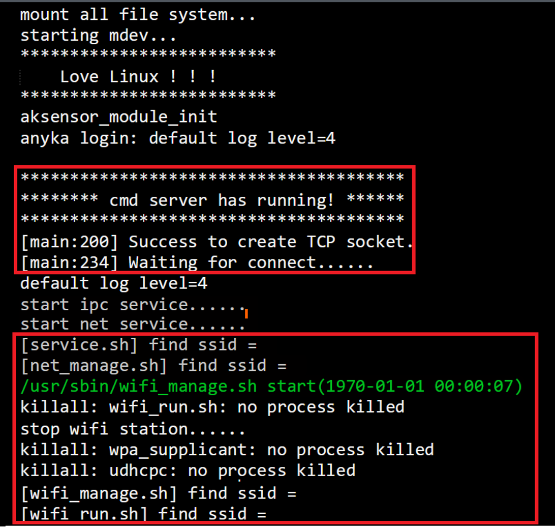
Once init is running, we can start seeing various functions and services being start/run!
There are a few interesting things to note right away for me,
1: CMD SERVER is running and is listening on TCP sockets… but what port?
2: There are a lot of calls to .sh scripts. Generally, scripts have a lot of extra info and maybe permission issues (can we exploit these at a later stage)
3: 4 Different scripts are referencing “find ssid =”, but why? Is this something we can further affect?
Further down the running process of the Linux system we see something that catches my eye.
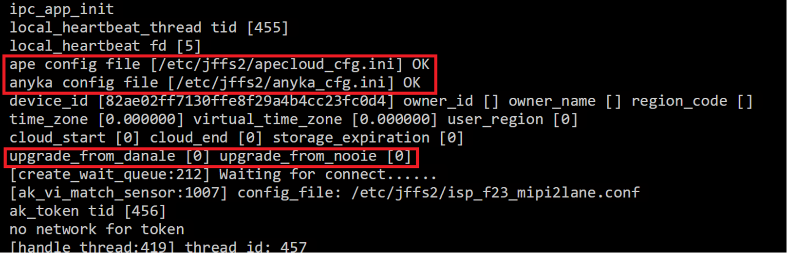
Config files are great for information disclosure purposes. They help answer a lot of questions!
Additionally in this image, there is references to upgrades… now from previous experience, having a upgrade function running at boot/startup time can sometimes be a way of forcing a malicious firmware to the device if its needed!
After this part the camera sorts itself out with light adjustments, fps adjustments, resolutions, audio controls, etc…
But then it gets to this part (this was mistake #2)
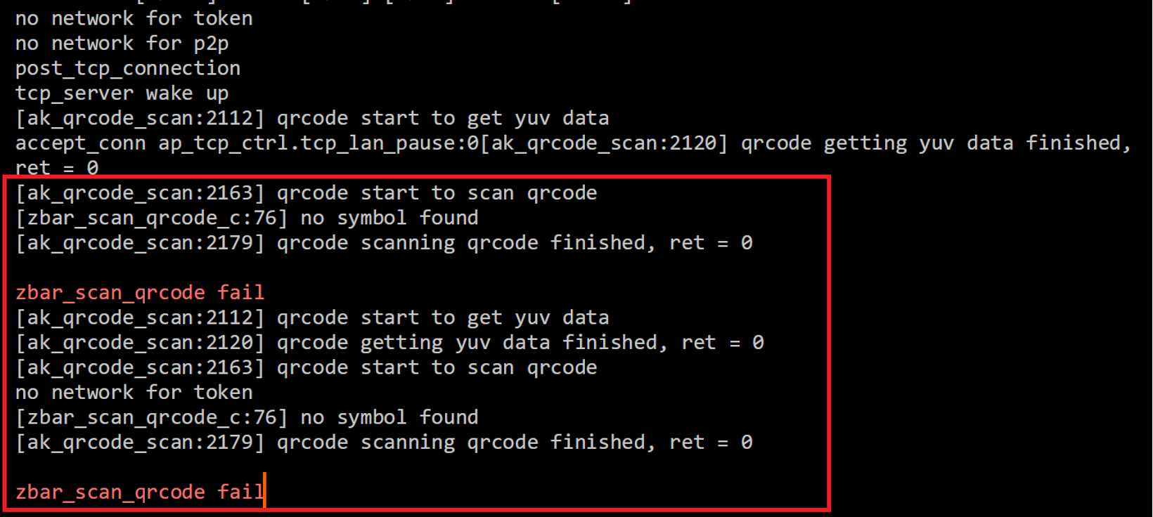
Now if I had read the instructions on how to set this device up, or even played with the camera from the beginning, I would have known it allows you to use a Wi-Fi QR code to easily get the camera connected to a network!
So I was surprised to see this!
But instantly I thought… hmmm, I wonder if that is a script or binary doing that function, and I wonder if its injectable from a security point of view??
Well, from all the above was enough to dig deeper into this camera!
Getting a shell:
As I alluded to earlier and you may have already seen, we can interrupt the U-Boot process and alter the Linux Kernal boot command.
So, after rebooting the camera, we force the U-Boot to halt and throw us into the U-Boot CLI.
We have several options here, but I won’t bore you. We are going to try and get a Linux shell!
From earlier we know we can change the bootargs to load the /bin/sh instead of /sbin/init
setenv bootargs console=ttySAK0,115200n8 root=/dev/mtdblock4 rootfstype=squashfs init=/bin/sh mem=64M memsize=64M
saveenv
reset
We let the device reset (don’t power off) and it will eventually drop into a bash shell.
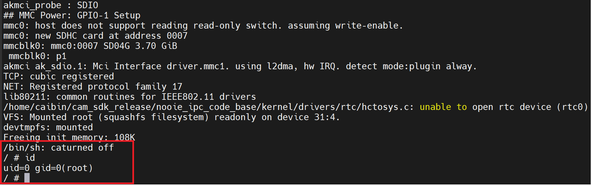
Yay! That’s it, Blog Done, Camera Pwned… 😉
Now that we have Gained a shell, and as ROOT, we can see what files are located where.
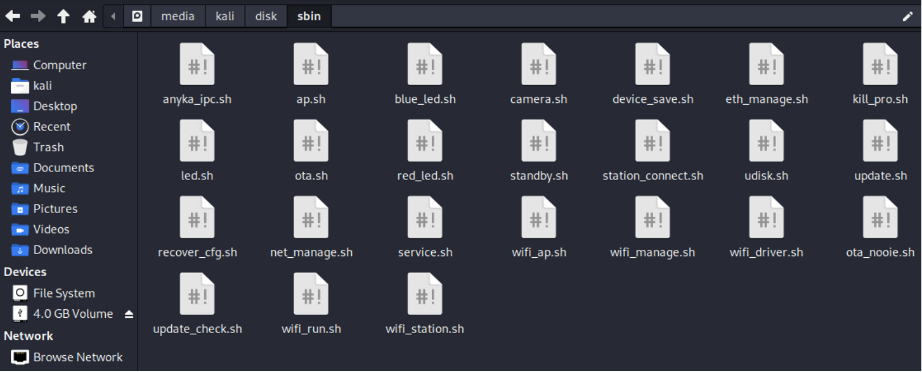
At this point, there are no bash scripts on the device (remember from earlier in the UART output it referenced things like “service.sh” “wifi_connect.sh”, well at the moment, they are still not mounted properly And that is because we interrupted the boot operation (init) to run our /bin/sh..
However, in the /etc/init.d/ directory we can see some scripts that do exist and give us hints to what the system is doing at boot time.
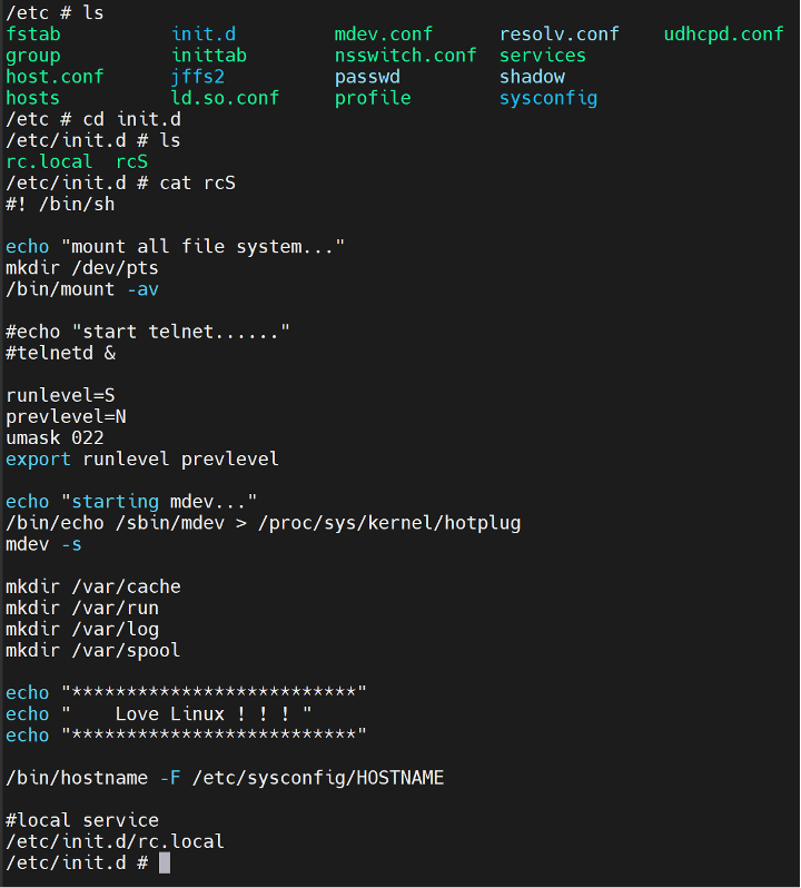
Notice how “telnetd” is commented out?
Anyways the “rcS” then points to the “rc.local” file and runs what’s in there too.
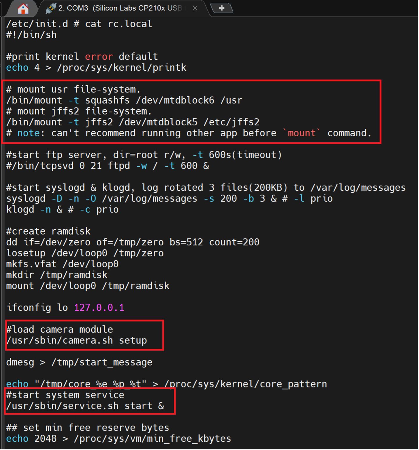
In the “rc.local” file, we can see it is actively mounting the different SPI flash blocks into specific directories. Then further down the script, it calls the bash scripts that we had seen earlier.
So, since we have a bash shell, can we use this to create a copy of the SPI flash blocks and throw them to an SD card? Since the device has SD card slot? Let’s try…
By inserting an SD card (FAT32 Formatted) to the SD card slot, we get a notification on the UART Shell that a card has been inserted.
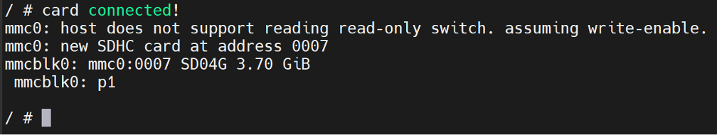
Now that we know where the SD card is “mounted” (“mmcblk0”) can we copy the files we want.
Yes, we can, so from the script above, we know the “usr” file system is on “mtdblock6” and “/etc/jffs2” is on “mtdblock5”.
cat /dev/mtdblock6 > /dev/mmcblk0p1 (/usr/)
cat /de/mtdblack5 > /dev/mmcblk0p1 (/etc/jffs2)
Each time, it will cat the block to the SD card, so it overwrites whatever was on the card originally, be aware.
For some random reason, the /etc/jffs/ partition didn’t want to be recognised strait away (the file system is JFFS and not instantly recognised by a Linux system), so easy way of getting around this is DD the SD card to a file, then use Binwalk to extract everything from the SD Card dump.
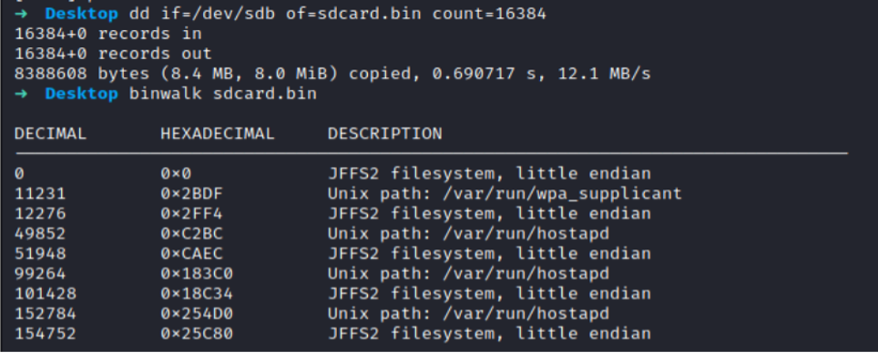
We can use binwalk to extract the JFFS2 Filesystem.
I generally use:
binwalk -Me –runas=root
Then take a peek at the extracts, in this instance, we can use Jefferson (https://github.com/sviehb/jefferson) to extract the JFFS2 file system from the extract.
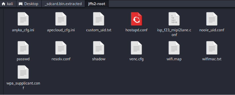
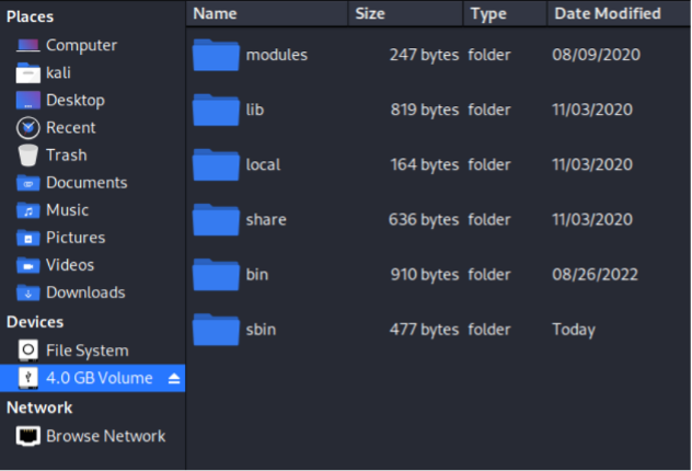
This folder is extracted on the device to the “/etc/jffs2” directory!
We now have the relevant folders copied from the device. EASY PEASY!
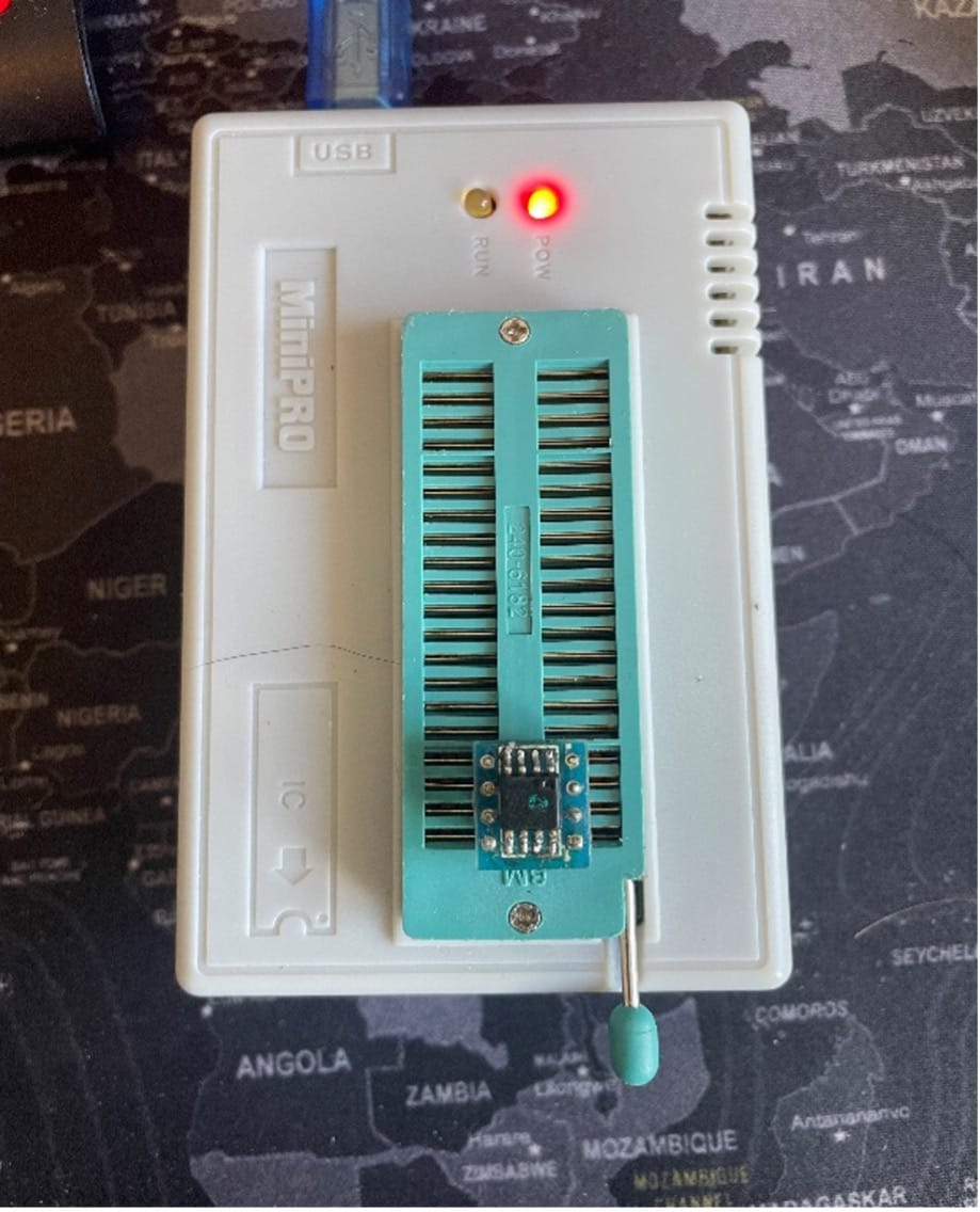
NOTE: We could have used the MMC commands in U-Boot too. OR we could have just dumped the SPI Flash chip like this!
Either way, we have the files.
Part 2 - Reverse Engineering the Binaries!